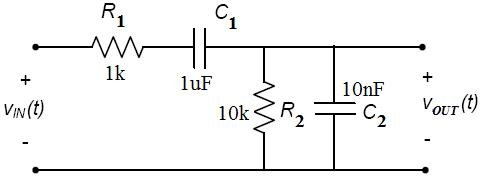
The circuit in figure 4 is used for measuring the junction temperature. To do this, the DUT must first be calibrated. By applying a small current through the diode and measuring the forward voltage, the temperature of the junction can be measured. The forward voltage of any diode is highly dependent on the temperature. However, this temperature can be determined indirectly. This temperature can't be measured with a thermometer because it's located within the diode casing and is very small. The junction temperature is the temperature of the PN depletion region in the silicon. 4: Circuit to measure the junction temperature. So, this temperature as to be determined first. The above explained that it is necessary to know the junction temperature to do a proper measurement on diodes. How the forward characteristic is measured correctly will be described further on. This example shows the importance of knowing the accurate junction temperature to get a reliable result. The true characteristic at a constant junction temperature is smoother and less steep. Due to this measurement error it looks like the curve has a very sharp bend and rises very steeply. For comparison, the diode characteristic whereof the junction temperature is held constant at 47 º, is shown as a red trace in the graph.īy this increase in temperature during the measurement an unreliable representation of the diode characteristic is acquired. This behavior is displayed as the blue trace in figure 3. As the current is further increased the dissipated power is growing and the junction temperature is increased along.

At the start where the current is still low, the self-heating is minor. The product of the diode current I D and diode voltage V D is the dissipated power that will warm-up the diode.

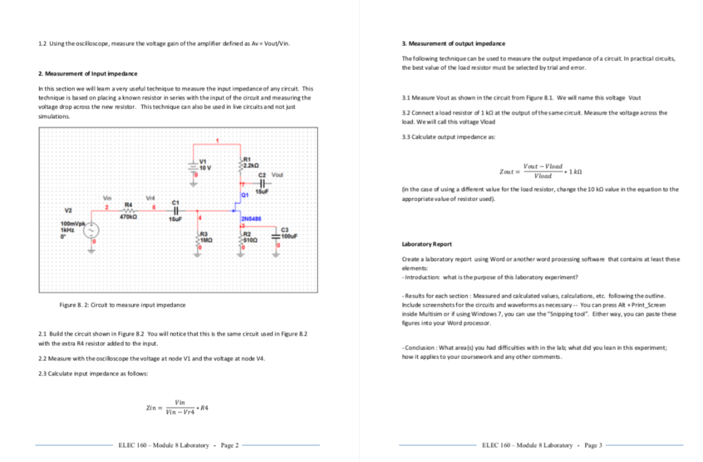
#Measure voltage gain in multisim 14.1 manual
3: The measuring current will increase the junction temperature which cause a distorted diode characteristic.īy doing such a manual measurement a constant current is flowing through the diode. The voltage drop across the diode is measured with the voltmeter V. At each voltage a the current through the diode DUT is measured with a amperemeter A. The curve is recorded by increasing the voltage V step by step. Or, if available, a adjustable current source an be used. The measuring current is set by the adjustable voltage source V and resistor R. The easiest way to obtain this curve is by using the circuit of figure 2.

It tells what the voltage drop will be at a given current. The voltage-current curve is the best known characteristic of a diode. 2: Basic circuit diagram to measure a diode characteristic.


 0 kommentar(er)
